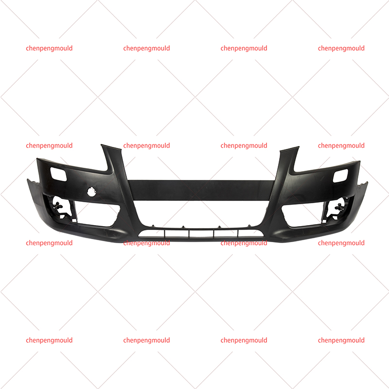
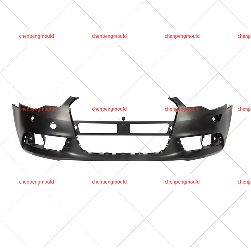
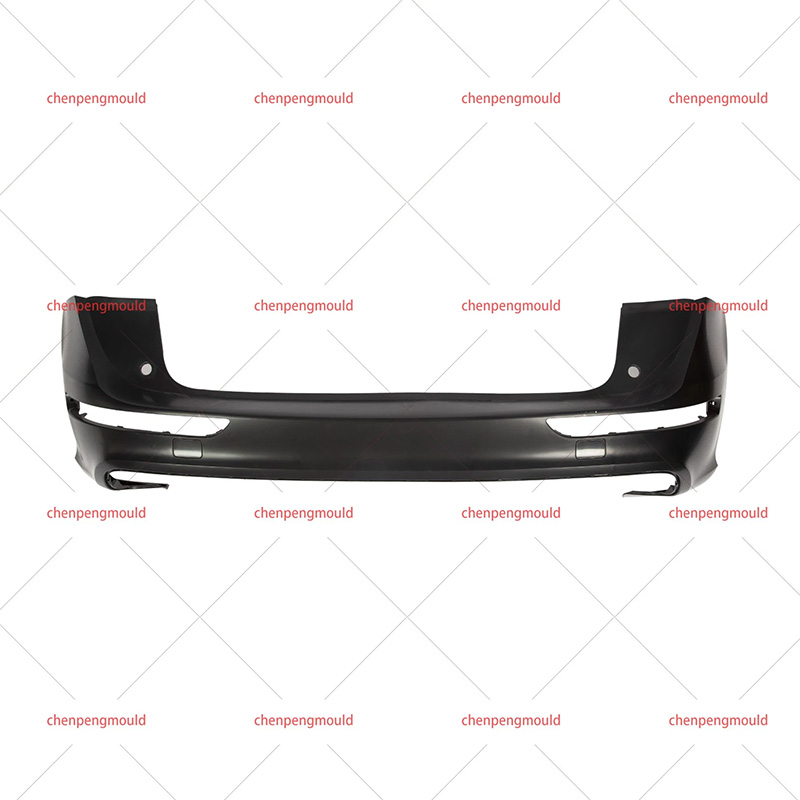
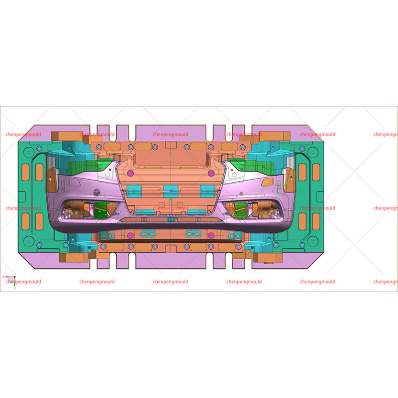
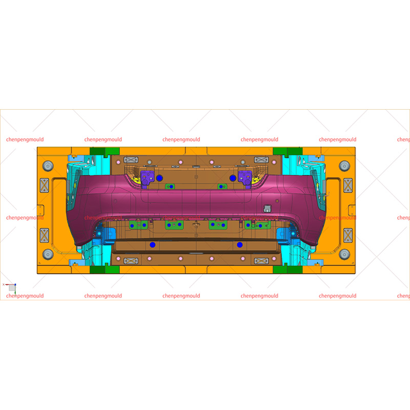
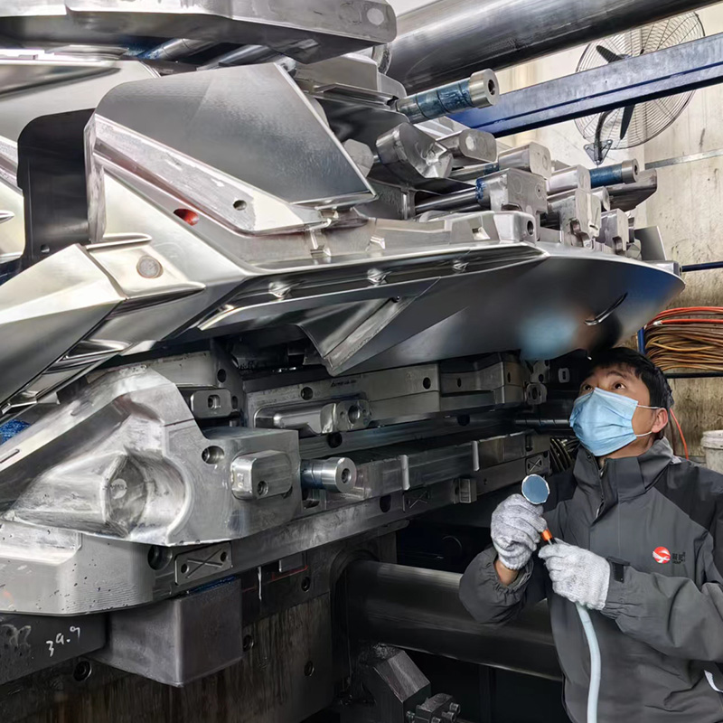
The auto bumper mold is a complex assembly of steel plates, slides, cores, cooling channels, and ejection systems. Its size—typically 1,800 mm × 600 mm × 800 mm—requires a frame made of forged or cast tool steel. The mold consists of two halves: the stationary half (A-side) attached to the injection unit, and the moving half (B-side) attached to the clamping unit. When closed, the two halves form a cavity with a volume of 8 to 15 liters, depending on bumper size.
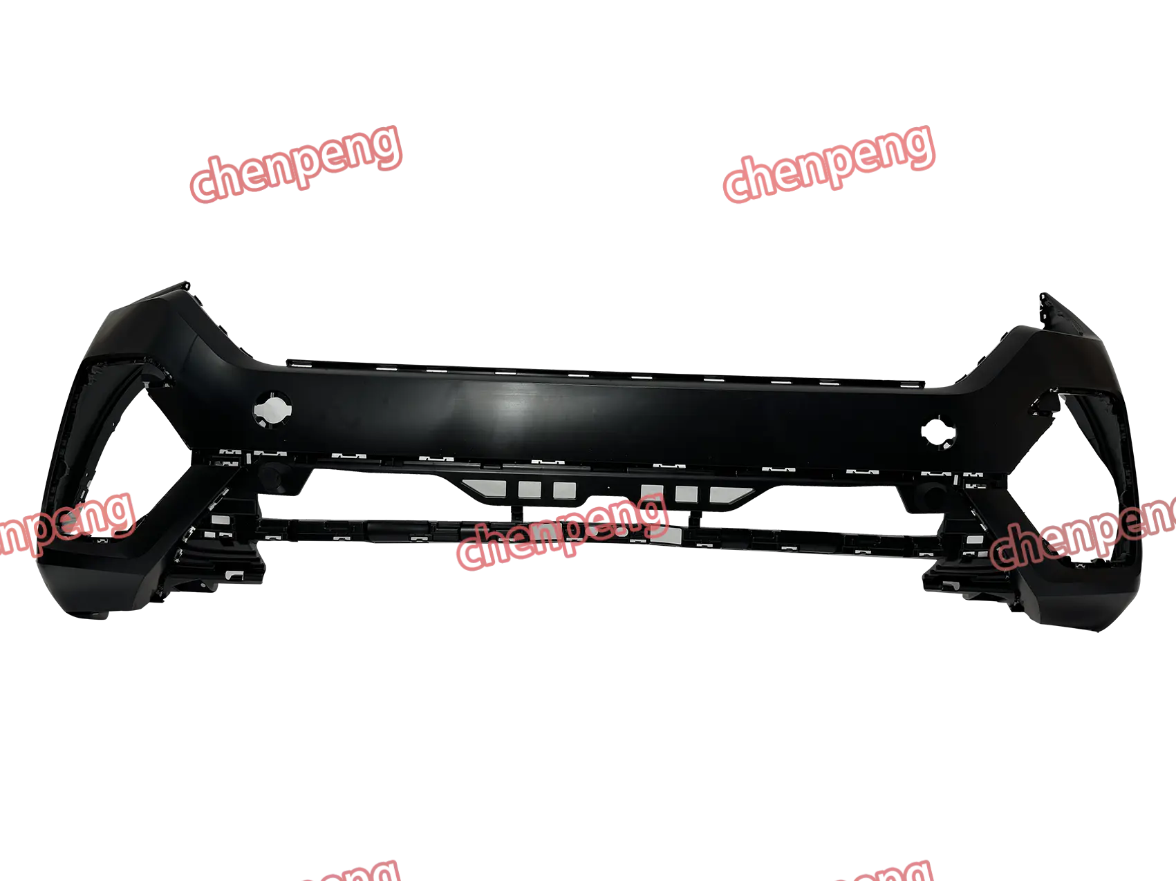
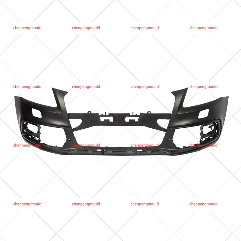
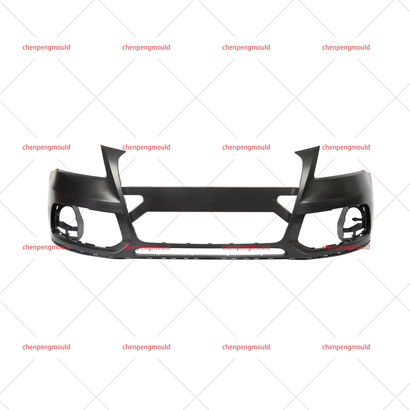
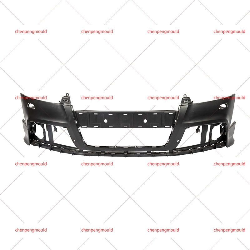
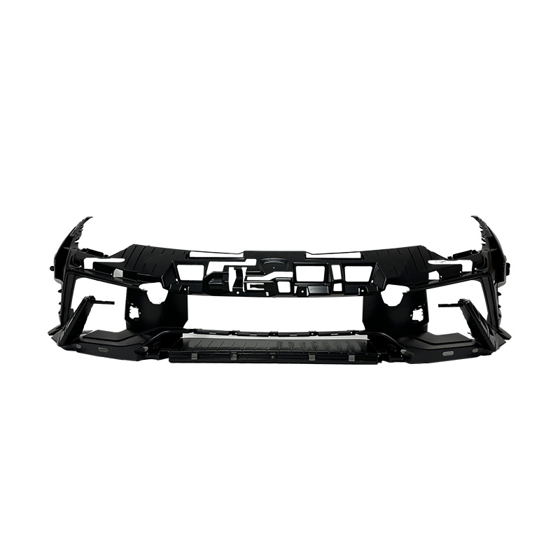
Cavity and core design. The A-side forms the outer surface of the bumper (painted surface), requiring a mirror finish of Ra 0.05–0.1 micrometers. The B-side forms the inner surface, which includes ribs, bosses, and mounting points. Ribs are typically 2–3 mm thick and 15–25 mm high, spaced 40–60 mm apart to provide structural rigidity without causing sink marks. Bosses for screw attachments have an outer diameter of 8–10 mm and an inner diameter of 4–5 mm, with steel inserts for threads.
Slides and lifters. Bumpers have undercuts—features such as fog lamp openings or tow hook covers that cannot be molded with straight pull. Slides (also called side cores) move perpendicular to the mold opening direction. Hydraulic or mechanical (angle pin) mechanisms retract slides before the bumper is ejected. A typical bumper mold has 4 to 8 slides, each weighing 50–200 kg. The clearance between slide and cavity is 0.02–0.05 mm; larger gaps produce flash (excess plastic).
Materials Used for Mold Components and Their Properties
The choice of material for each mold component directly affects mold life, cycle time, and part quality. The table below summarizes common materials and their applications.
|
Mold Component |
Typical Material |
Hardness (HRC) |
Thermal Conductivity (W/m·K) |
Wear Resistance |
Relative Cost |
|
Cavity and core plates |
P20 (modified tool steel) |
30–36 |
29 |
Medium |
1.0 (baseline) |
|
Wear-resistant inserts |
H13 or D2 tool steel |
48–52 |
24 |
High |
2.5 |
|
Slides and lifters |
420 stainless steel |
42–46 |
25 |
High (corrosion-resistant) |
3.0 |
|
Cooling channel baffles |
Copper alloy (beryllium-free, e.g., C18000) |
20–25 |
200–250 |
Low |
8.0 |
|
Ejector pins |
M2 high-speed steel |
58–62 |
24 |
Very high |
4.0 |
|
Guide pillars and bushings |
Steel with bronze coating |
55–60 (steel) |
45 (bronze) |
High |
2.0 |
Cavity and core plates. P20 steel (equivalent to DIN 1.2311 or AISI P20) is pre-hardened to 30–36 HRC, allowing machining without final heat treatment. For production runs exceeding 500,000 parts, mold makers use H13 steel hardened to 48–52 HRC, which extends cavity life to 2 million cycles but increases machining cost by 40%.
Slides and lifters. 420 stainless steel resists rust from coolant water and condensation. Slide surfaces that contact the cavity require wear plates made of bronze or graphite-impregnated material, reducing friction coefficient from 0.6 (steel-on-steel) to 0.15.
Cooling components. Copper alloy baffles and bubblers (turbulence promoters) increase heat transfer because copper conducts heat 8–10 times better than steel. A copper baffle inserted into a cooling channel can reduce cycle time by 10 seconds for a 60-second cycle. However, copper alloys are softer than steel and must be replaced every 100,000–200,000 cycles.
Cost-performance trade-offs. For a mold expected to produce 300,000 bumpers over five years, P20 steel with standard cooling channels is sufficient. For 1 million bumpers over eight years, H13 cores with conformal cooling and copper baffles reduce per-part cost despite higher initial mold cost ($200,000 vs. $120,000). The break-even point is approximately 700,000 parts.
Manufacturing Steps and Tolerances in Mold Production
Producing an auto bumper mold requires 8 to 16 weeks and involves five major manufacturing stages.
1. Rough machining. The steel blocks (typically 2,000 kg for the B-side plate) are rough-milled to within 2–3 mm of final dimensions. Large horizontal milling machines with 50–100 HP spindles remove material at rates of 300–500 cm³ per minute. Roughing leaves a 0.5–1.0 mm stock for finishing.
2. Heat treatment (if required). For H13 steel, the rough-machined plates undergo vacuum hardening: heating to 1020–1050°C, holding for 30–60 minutes, then gas quenching to 50°C. Tempering at 550–600°C for two hours achieves 48–52 HRC. Distortion during heat treatment is typically 0.1–0.3 mm, requiring subsequent finishing.
3. Finishing and electrode machining. Cavities are finished with ball-nose end mills (6–12 mm diameter) running at 10,000–20,000 RPM. For hard steel (48 HRC), finishing passes remove only 0.05–0.10 mm per pass. Complex features—textured surfaces or deep ribs—are cut using electrical discharge machining (EDM). A graphite electrode is machined to the negative shape of the feature and discharges sparks that erode the steel. EDM achieves tolerances of ±0.02 mm but requires 2–4 hours per electrode.
How Is Quality Verified Before and During Production?
Quality control for an auto bumper mold occurs at three stages: during mold manufacturing (dimensional inspection), before production (trial molding), and during ongoing production (in-process checks).
Dimensional inspection of the mold. After finishing, each cavity surface is measured using a coordinate measuring machine (CMM) with a probe accuracy of ±0.003 mm. For a bumper mold, 200–400 points are measured, including critical dimensions: mounting boss positions (±0.10 mm), rib thickness (±0.05 mm), and slide path clearances (±0.02 mm). Any dimension outside tolerance triggers re-machining or EDM correction. The mold’s parting surface (where A and B halves meet) is checked for flatness using a feeler gauge. A 0.05 mm feeler should not insert more than 10 mm along any 100 mm segment of the parting line.
Trial molding. The mold is installed in an injection molding machine and produces 50–200 sample bumpers. These samples are measured for: overall length and width (±1.0 mm tolerance per vehicle manufacturer specification), rib presence and fill (no short shots), sink marks (depth less than 0.1 mm measured with a profilometer), and flash (excess plastic extending less than 0.2 mm from parting line). Trial bumpers are also impact-tested according to ISO 6605 or equivalent: a 4 kg pendulum striker hits the bumper at 4 m/s (energy 32 J). The bumper must not crack or fracture; only minor surface whitening is allowed.

 +86-18357617666