

 عربى
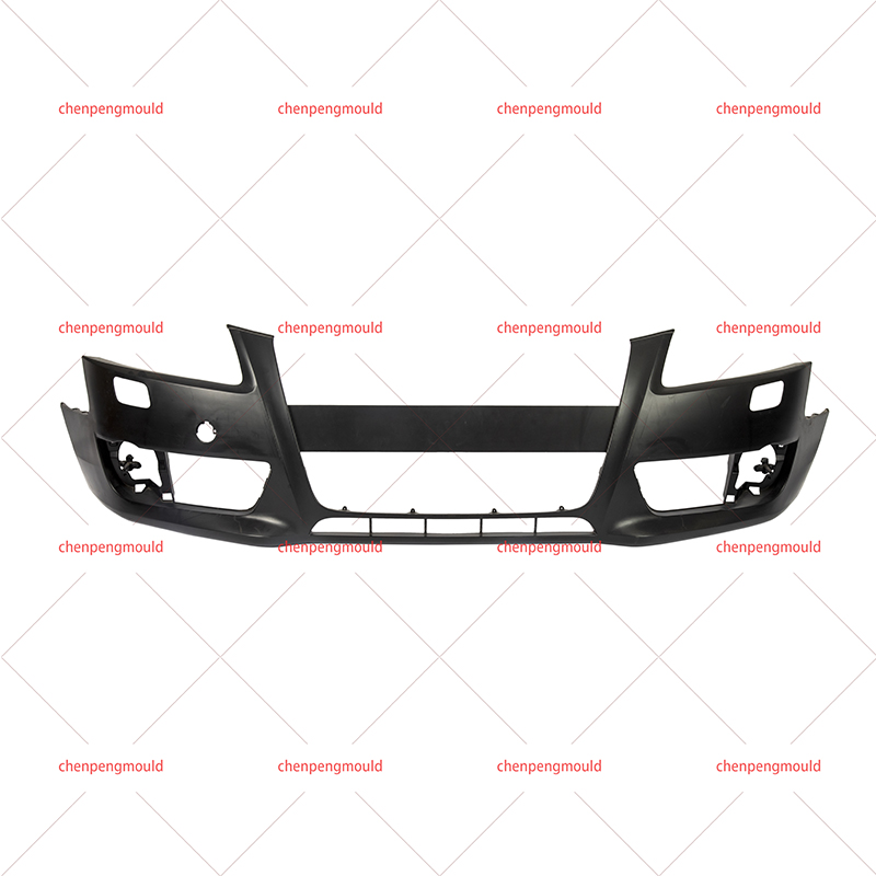
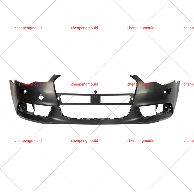
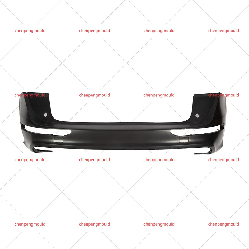
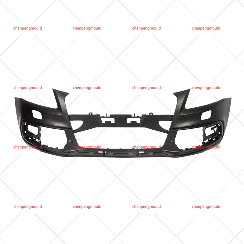
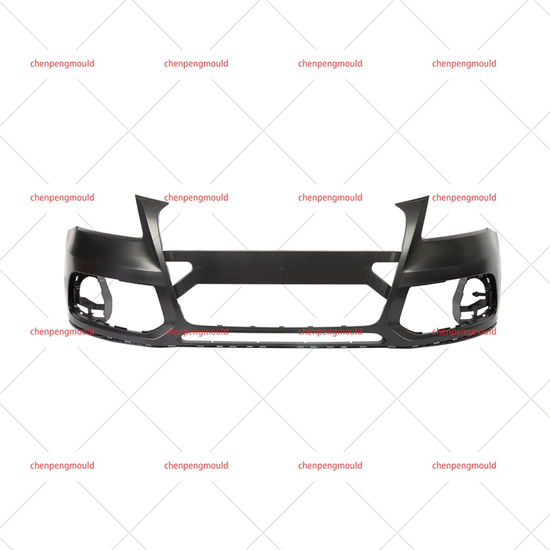
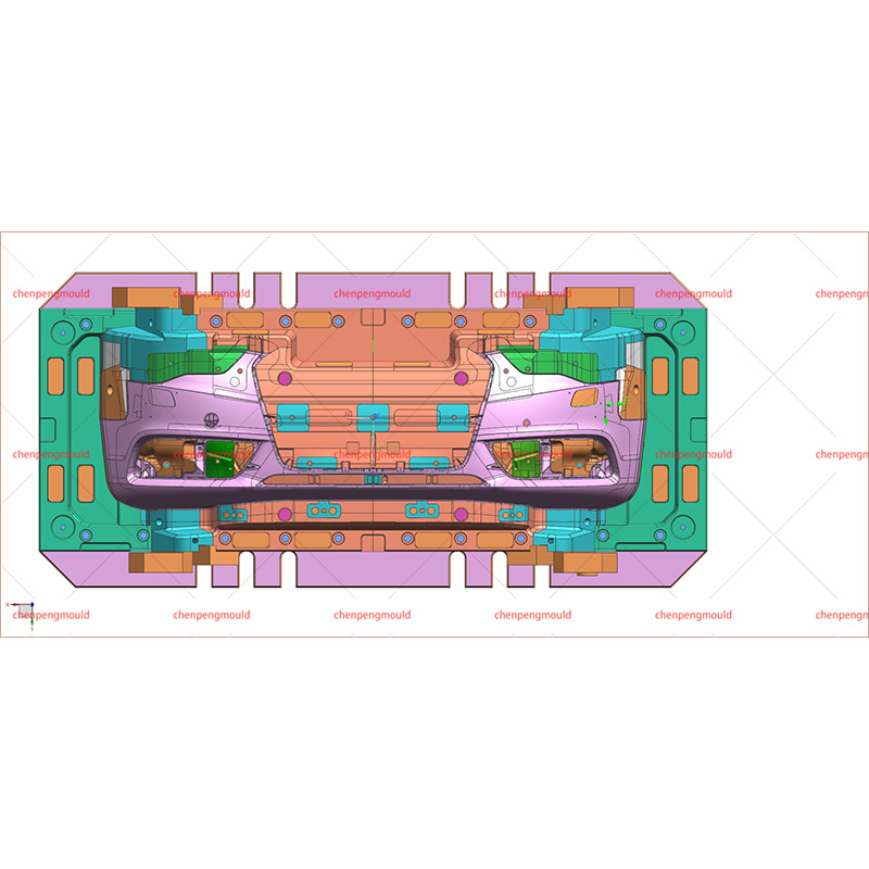
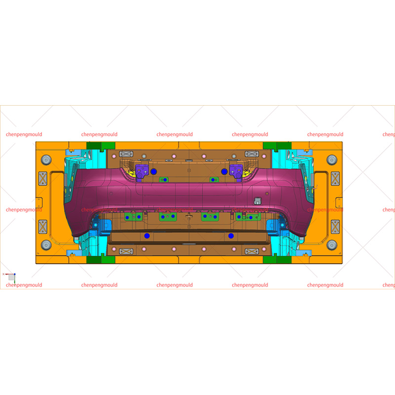
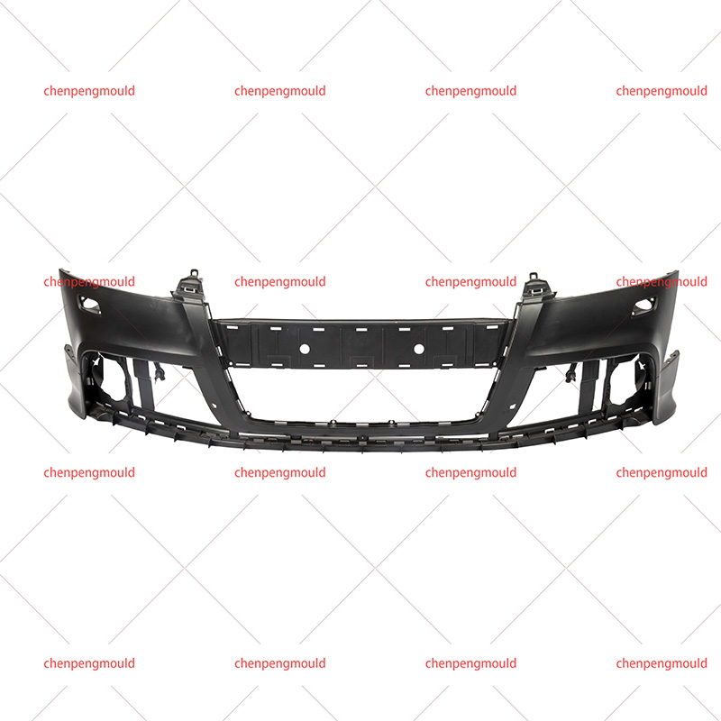
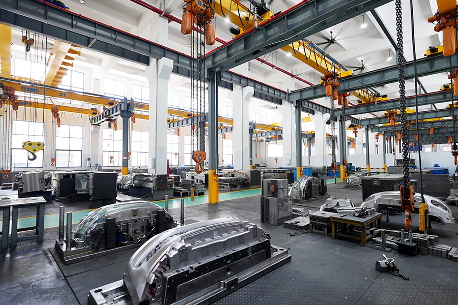
عربىModern vehicle bumpers are becoming wider, more sculpted, and increasingly integrated with openings for lamps, grilles, sensors, and other functional elements. Such geometry creates a demanding tooling environment. A Large Automotive Bumper Injection Mold must handle long flow distances, thin walls, complex curves, large cosmetic surfaces, and significant thermal variation within a single molding system.
The challenge is not simply making the cavity large enough. Every additional section of a bumper can influence how molten plastic fills, cools, shrinks, and finally releases from the mold.
Long Flow Paths Change the Filling Strategy
Bumper fascia designs often combine a large projected area with relatively thin walls. Plastic traveling across a long cavity gradually loses pressure and temperature, making filling more difficult toward distant regions.
- Longer flow distance: Requires careful control of pressure and melt temperature.
- Thin-wall sections: Can freeze earlier and restrict downstream filling.
- Large surface area: Makes small variations in shrinkage more visible.
- Complex openings: Can interrupt the natural flow path and change pressure distribution.
Research and industrial tooling references identify long flow length relative to wall thickness as a major issue for large automotive components. Sequential valve gating can help control melt-front advancement and reduce excessive pressure concentration in certain regions.
Gate Location Becomes a Cosmetic Decision
Gate placement is not purely about getting plastic into the cavity. On an exterior bumper, weld lines, gate vestiges, flow marks, and gloss differences can become visible on painted or unpainted surfaces.
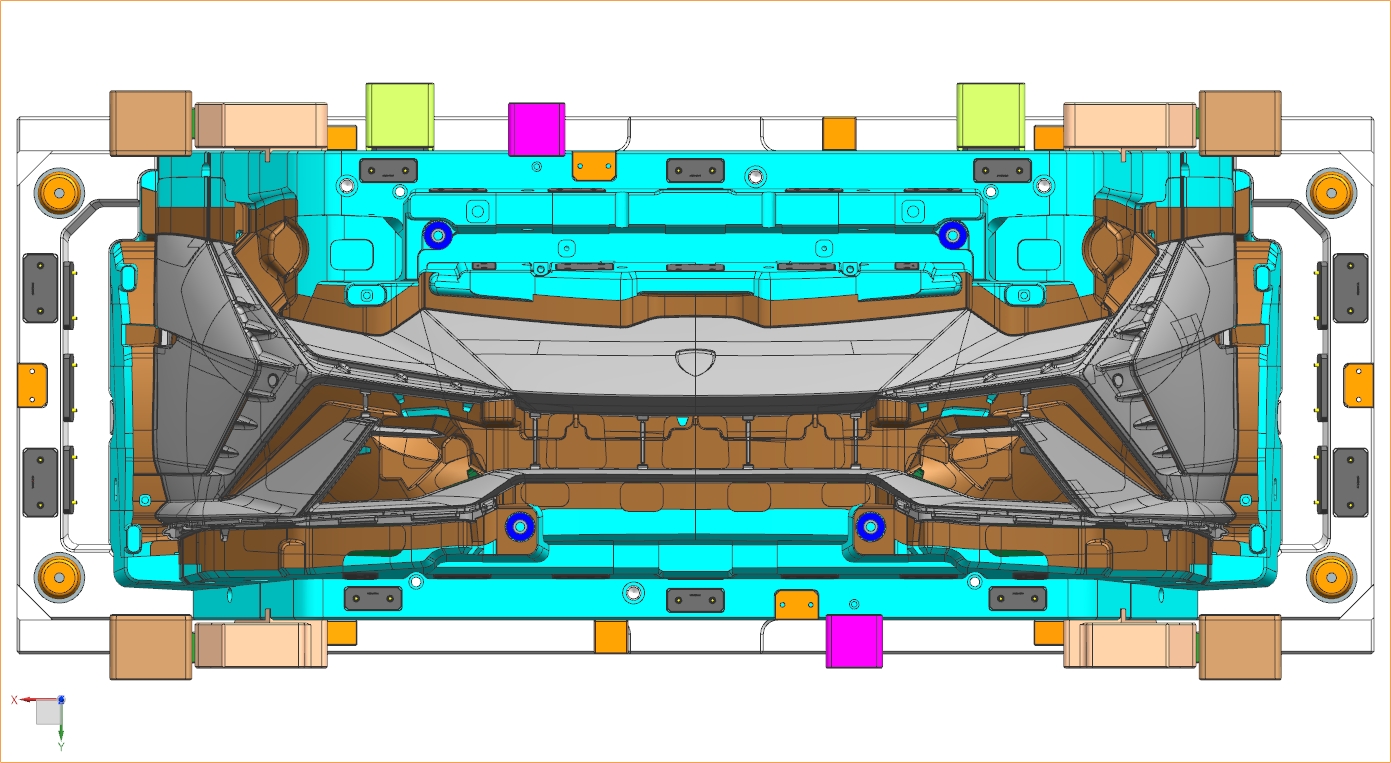
A Large Automotive Bumper Injection Mold may therefore use several hot-runner gates instead of relying on a single injection point. Sequential valve control allows individual gates to open at programmed stages as the melt front advances.
- Controls the position of weld lines.
- Helps distribute filling pressure across the cavity.
- Reduces excessive packing around early-filled regions.
- Provides greater control over flow direction.
One documented bumper tooling case used ten injection points with sequential valve control. After changes to gate positions and cooling, the reported warpage decreased from 7.4 mm to 5.8 mm.
Why Seven or Ten Gates Are Not Automatically Better
Adding gates does not automatically solve large-part filling problems. Each additional gate creates another flow front that has to be coordinated with the others.
Gate timing can influence where flow fronts meet. Opening a downstream valve too early may create an undesirable weld line or pressure interaction, while opening it too late can leave the material colder before reaching a distant section. Research on sequential valve gating highlights its role in controlling pressure, flow-front movement, and structural or cosmetic defects in large molded components.
Key Variables During Gate Development
- Gate quantity and position
- Valve opening sequence
- Injection speed
- Melt temperature
- Cavity pressure
- Packing transition
- Weld-line location
Cooling Has to Follow the Bumper Geometry
Large bumper cavities rarely have uniform geometry. Thin outer walls, reinforcing ribs, mounting bosses, deep core sections, and gate regions can all behave differently during cooling.
Uneven cooling creates different shrinkage rates across the component. The resulting deformation may appear as bowing, twisting, edge distortion, or dimensional movement around mounting locations. Large automotive tooling references specifically identify cooling balance as a critical factor for controlling warpage and dimensional stability.
- Cosmetic areas: Need stable temperature distribution to reduce surface variation.
- Deep cores: May require additional cooling attention because heat can remain concentrated.
- Thick mounting zones: Can continue shrinking after thinner sections have solidified.
- Gate regions: Need thermal management around hot-runner components.
Structural Rigidity Matters at This Scale
The physical size of the mold creates another engineering concern: cavity and core structures must remain stable under injection and clamping loads.
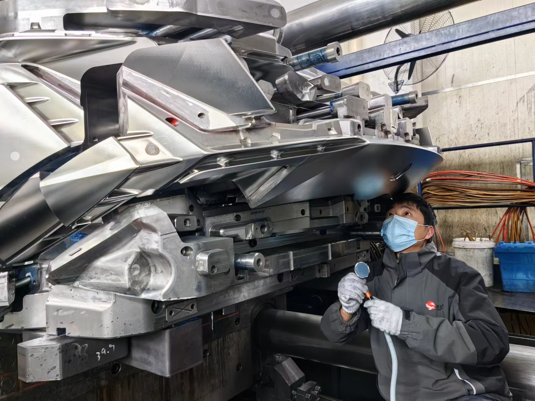
Large tooling may contain sliders, lifters, inserts, ejector systems, cooling circuits, and hot-runner components within a substantial mold base. Removing material or reducing structural sections without evaluating load paths can affect alignment and cavity stability.
Finite element analysis can help identify areas that require additional support. Mold structure, cooling access, ejection layout, and maintenance space also need to be considered together rather than designed as isolated systems.
Material Choice Changes the Mold Requirements
Bumpers commonly use materials such as PP-based compounds and TPO because impact performance, flexibility, weight, and appearance are important considerations. Reinforced grades can introduce another variable because fiber orientation may influence shrinkage and deformation.
Gate position therefore affects more than filling. Flow direction can influence fiber orientation in reinforced materials, which can subsequently affect dimensional behavior.
Large Mold Design Starts Before Steel Cutting
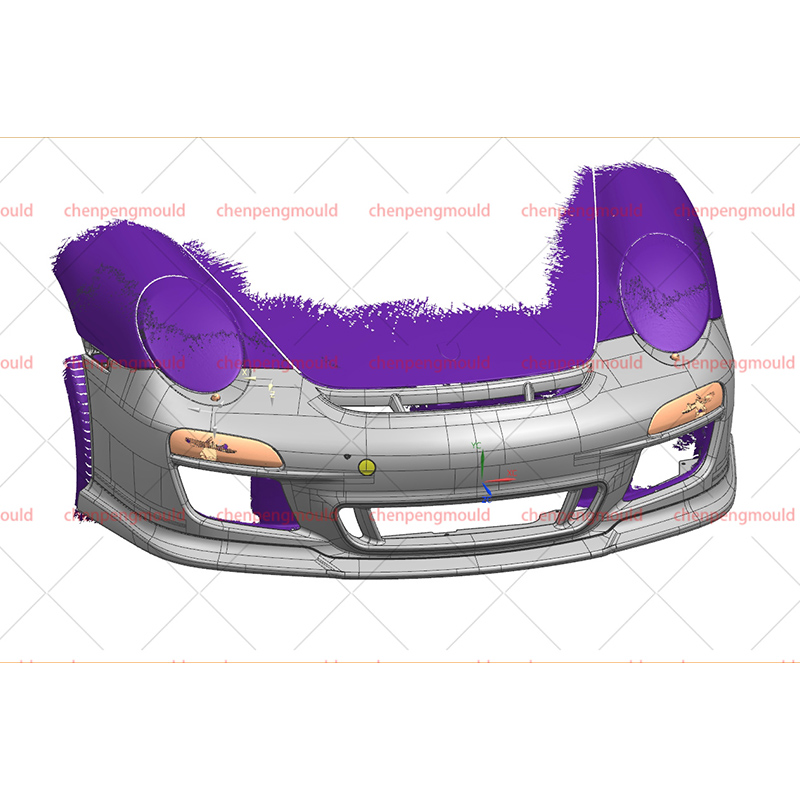
Trying to correct a major filling or warpage problem after machining a large mold can involve substantial modification work. DFM and Mold Flow analysis provide an opportunity to examine potential issues before the cavity is completed.
- Review wall-thickness transitions.
- Map potential weld-line locations.
- Evaluate gate quantity and sequence.
- Check injection pressure and clamping requirements.
- Analyze cooling coverage.
- Predict shrinkage and warpage.
- Review slider, lifter, and ejection movements.
Current large-part injection molding guidance recommends addressing part geometry, gating, cooling, ejection, and structural requirements during early mold engineering rather than treating them as separate stages.
Where Does Bumper Mold Design Get Critical?
The difficult areas of a Large Automotive Bumper Injection Mold are interconnected. A gate change can alter the weld-line position. The same change can modify pressure distribution and cooling requirements. A wall-thickness transition can influence filling as well as shrinkage. A structural rib can affect both part stiffness and local cooling.
That is why large bumper tooling requires more than simply scaling up a conventional injection mold. The mold has to coordinate flow, pressure, temperature, structure, ejection, and surface appearance across a component that may span the entire front or rear width of a vehicle.
Longer bumpers do not necessarily require complicated tooling everywhere. They require careful engineering at the locations where geometry, flow, cooling, and appearance interact. Those critical zones ultimately determine whether the finished bumper leaves the mold with the shape, surface quality, and dimensional stability expected from modern automotive production.
 +86-18357617666