A batch comes off the line and two components that should be identical fit differently at the assembly point. The gap is small — a fraction of a millimeter — but it is enough to cause a misalignment that slows the line, triggers a quality hold, or creates a warranty issue downstream. If that pattern sounds familiar, the question is usually not about the assembly process itself. It is about the mould. An Auto Parts Mould that is correctly designed, properly maintained, and matched to the material and process conditions is what keeps every shot consistent across thousands of cycles. Without that foundation, production variation is not a line problem — it is a tooling problem that no amount of downstream adjustment can fully correct.
What an Auto Parts Mould Actually Does in Production
The Mould Is the Definition of the Part
Every vehicle component produced through injection moulding, compression moulding, or blow moulding takes its shape, dimensions, and surface character from the mould cavity. The mould does not just shape the part — it defines it. Wall thickness, parting line position, gate location, draft angles, and surface texture are all determined at the mould design stage and replicated in every shot thereafter.
This is why mould quality is not separable from component quality. A mould with dimensional inaccuracies, surface defects, or poorly designed cooling channels produces inaccurate, defective, or inconsistently cooled parts — regardless of how well everything else in the process is controlled.
How Does Consistency Get Built Into the Mould?
Consistency is not an accident. It is the result of deliberate decisions made during mould design and manufacture:
- Steel grade selection: The mould material affects dimensional stability under repeated thermal cycling and mechanical load. Harder steel holds tolerances longer under high-volume production.
- Cavity and core machining precision: The dimensional accuracy of the finished part is bounded by the precision of the machined cavity. CNC machining with fine tolerances at the tooling stage becomes the ceiling for part consistency.
- Cooling channel design: Uniform cooling across the part cross-section reduces warpage and dimensional variation caused by differential shrinkage. Poorly positioned or undersized cooling channels are a cause of part-to-part variation in injection moulded components.
- Venting design: Trapped air in poorly vented moulds creates surface defects, burn marks, and incomplete fills. Consistent venting produces consistent surface quality.
The Mechanism: How Injection Moulding Achieves Repeatability
Material Behavior Under Controlled Conditions
When molten polymer enters the mould cavity, its behavior during filling, packing, and cooling determines the final part geometry. Each of those phases is controlled through process parameters — injection speed, pack pressure, hold time, mould temperature, and cooling time. The mould itself is the fixed variable that determines how those parameters translate into part geometry.
A well-designed Auto Parts Mould allows the process parameters to work as intended. It fills uniformly, cools evenly, and releases the part without distortion. When the mould is working correctly, adjusting the process parameters produces predictable, repeatable changes in the part.
Why Multi-Cavity Moulds Require Additional Design Attention
High-volume vehicle component production often uses multi-cavity moulds — a single mould producing several identical parts per shot. Consistency across cavities requires that the melt reaches each cavity at the same time, at the same temperature, and at the same pressure.
Runner balance — the design of the channels that carry melt from the sprue to each cavity — is critical in multi-cavity tooling. An unbalanced runner system fills some cavities faster than others, which produces variation in packing pressure and, ultimately, dimensional variation between parts from different cavities.
This is a design problem that cannot be corrected at the press. It has to be addressed in the mould.
Key Components That Affect Dimensional Consistency
The Ejection System and Part Release
How a part is ejected from the mould affects its post-mould dimensions. A part that is ejected too early — before it has cooled sufficiently — deforms under the force of the ejector pins. A part that is gripped unevenly by the ejection system warps as it is pushed out of the cavity.
Ejector pin layout, pin diameter, and the timing of ejection are all mould design decisions that affect part quality. In components with thin walls or complex geometry — common in interior trim, air duct systems, and structural brackets — ejection design is as important as cavity design.
Does the Gate Location Change the Part?
Yes — significantly. The gate is the point where molten material enters the cavity, and its location determines the flow path through the part. Flow path affects:
- Weld line position (where two flow fronts meet and can create a weakness)
- Fiber orientation in filled materials (which affects mechanical properties)
- Sink mark location (where material shrinks away from the surface as it cools)
- Residual stress distribution (which affects dimensional stability after demoulding)
Gate location is fixed once the mould is built. Getting it right during design prevents downstream problems that are expensive to correct.
Hot Runner vs Cold Runner Systems
The runner system — the channels that deliver melt to the cavity — affects both part quality and production efficiency. The two main configurations behave differently in Auto Parts Mould applications:
| Feature | Cold Runner | Hot Runner |
|---|---|---|
| Material waste | Runner is ejected as scrap | No runner waste |
| Cycle time | Longer (runner must cool) | Shorter (no runner cooling) |
| Gate mark | Visible at cold gate point | Minimal with valve gate |
| Initial cost | Lower tooling cost | Higher tooling cost |
| Color change | Straightforward | Requires purging |
| Cavity pressure control | Limited | Valve gates allow precise control |
For high-volume automotive production, hot runner systems are common in larger components where material savings and cycle time advantages accumulate across production volumes. Cold runner systems remain practical for smaller components and lower volume tooling.
Surface Finish and Its Role in Component Quality
Texture Consistency Across a Production Run
Surface texture in automotive components serves functional and visual purposes. Interior trim components need consistent texture to meet appearance standards. Structural components may need specific surface conditions to accept adhesive bonding or overmoulding.
The surface finish of the mould cavity transfers directly to the part. Polished steel produces a glossy surface. Textured steel — through EDM, chemical etching, or mechanical texturing — produces a matte or patterned surface. Both types of finish wear over production cycles, which means surface consistency degrades as the mould ages.
Tracking surface condition as part of a mould maintenance program — and scheduling re-texturing or re-polishing at defined intervals — is how manufacturers maintain appearance consistency across the production run.
What Causes Surface Defects in Injection Moulded Auto Parts?
Surface defects on moulded vehicle components typically trace back to one of several causes:
- Sink marks: caused by insufficient pack pressure or cooling in thick sections
- Weld lines: where two flow fronts meet, usually visible as a line on the surface
- Short shots: incomplete filling, usually from inadequate injection pressure or mould temperature
- Flash: thin fins of material at the parting line, caused by worn steel or excessive injection pressure
- Burn marks: from trapped gas in poorly vented areas
- Delamination: caused by contamination in the material or moisture in hygroscopic resins
Each of these defect types has a root cause that connects to either mould design, mould condition, or process parameters. Diagnosing which factor is responsible requires understanding how the mould and process interact.
Materials Used in Auto Parts Mould Manufacturing
Steel Grade Selection Affects Mould Life
The steel used to manufacture the mould determines how long it holds its dimensions under production conditions. Automotive production runs are typically long — the same mould may cycle hundreds of thousands of times over its service life. Under repeated thermal and mechanical stress, softer steels deform and wear faster than harder grades.
Common considerations in steel selection for Auto Parts Mould applications:
- Hardness requirements: Higher-volume moulds benefit from harder steel that resists wear at the parting line and cavity surface
- Machinability: Some harder steels require specialized cutting tools and extended machining times, which affects tooling schedule and cost
- Corrosion resistance: Moulds running glass-filled or abrasive materials wear faster and may benefit from surface treatments that extend cavity life
- Heat treatment: Pre-hardened steel simplifies post-machining requirements; through-hardened steel requires heat treatment after rough machining but before finishing
Can Mould Inserts Extend Tool Life?
Yes. Inserts — replaceable sections of the mould cavity — allow the areas with elevated wear to be replaced without rebuilding the entire mould. This is a practical strategy for areas near the gate, at parting lines, and in thin ribs or cores that wear faster than the surrounding cavity.
Designing mould inserts into the original tooling is a cost-management decision that pays off in longer tool life and lower maintenance cost over a production program.
Mould Maintenance and Its Effect on Component Consistency
What Happens to a Mould Without Maintenance?
A mould that runs without regular maintenance produces progressively less consistent parts. The changes are gradual, which makes them easy to miss in routine quality checks until the variation accumulates to a level that triggers a non-conformance.
Common maintenance-related consistency issues:
- Parting line wear allows flash to develop, which creates deburring requirements and surface quality issues
- Cooling channel fouling reduces cooling efficiency, which extends cycle time and increases part-to-part temperature variation
- Ejector pin wear allows parts to stick in the cavity, which can cause deformation during ejection
- Surface finish degradation in textured areas creates visible inconsistency in appearance
A Structured Maintenance Schedule Protects Part Quality
Maintenance scheduling for Auto Parts Moulds typically runs on two levels:
- Preventive maintenance at defined cycle intervals — cleaning, inspection, lubrication, and minor adjustments performed before failure occurs
- Corrective maintenance triggered by observed quality shifts — addressing specific wear or damage as it is detected
The cycle interval for preventive maintenance depends on the mould material, the material being moulded, and the production conditions. A mould running abrasive glass-filled material needs more frequent attention than one running standard unfilled polypropylene.
Mould Design for Specific Vehicle Component Types
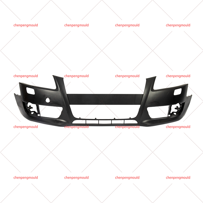
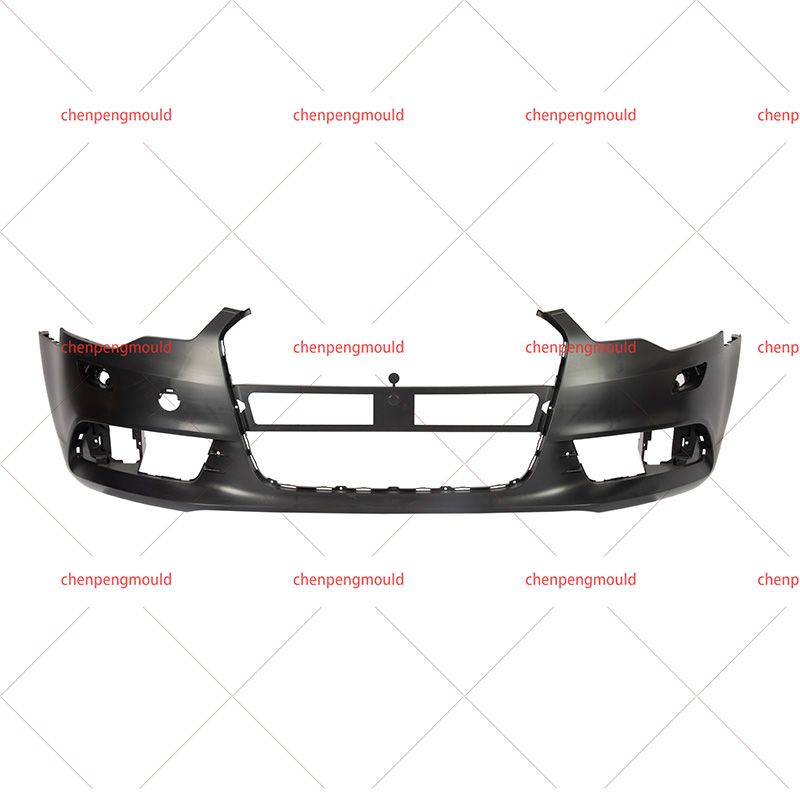
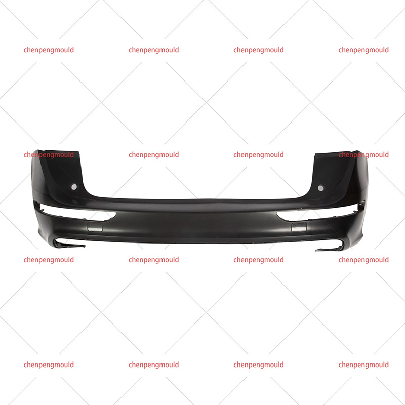
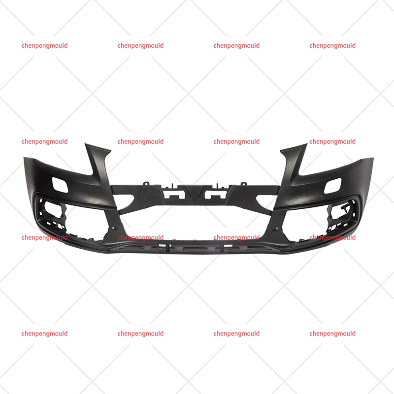
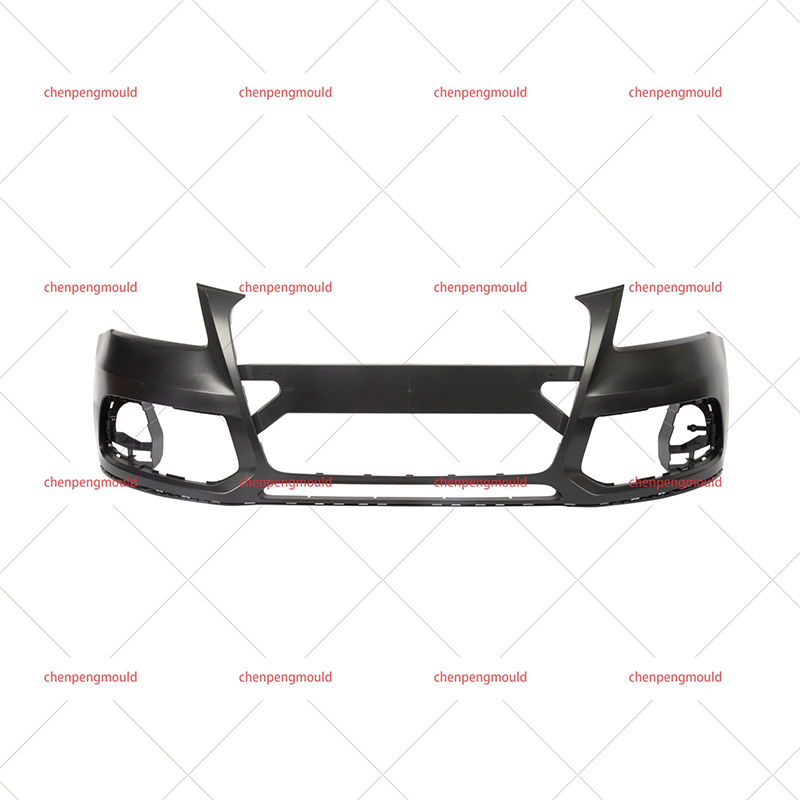
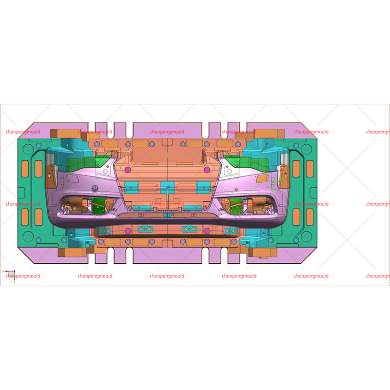
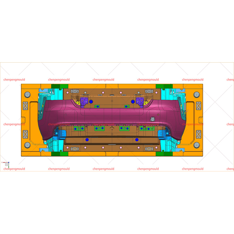
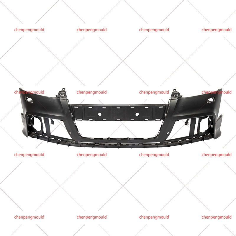
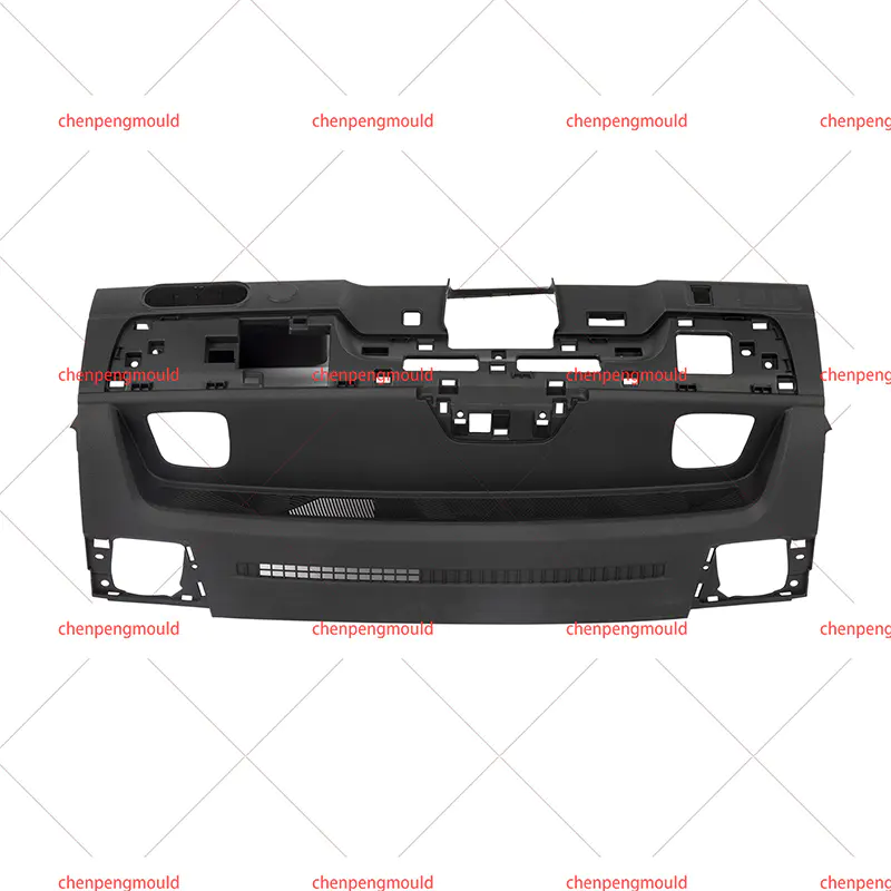
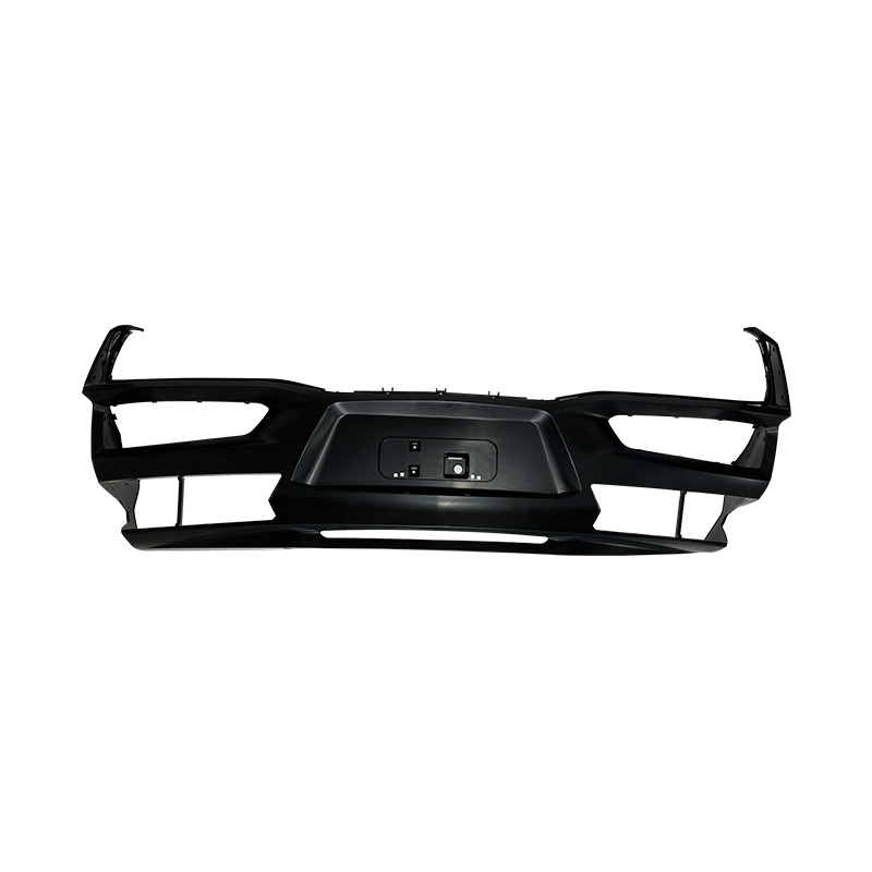
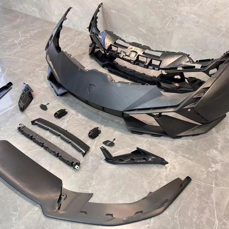
Exterior Body Panels and Bumpers
Exterior components have stringent appearance requirements — surface texture, gloss level, and parting line position all affect how the finished vehicle looks in assembly. Moulds for these components are typically large, require precise surface finishing, and use hot runner systems to achieve the fill consistency needed for uniform appearance across the part.
Cooling design is particularly critical for large flat sections, where differential cooling causes warpage that affects fit during body assembly.
Structural Under-Hood Components
Components in the engine bay face temperature cycling, chemical exposure, and mechanical load in service. The mould needs to produce parts with consistent wall thickness and structural geometry that meet the mechanical performance requirements.
Gate location and flow path design directly affect fiber orientation in reinforced materials, which determines the directional strength of the finished part. These are engineering decisions made at the mould design stage, not adjustments that can be made later.
Interior Trim and Clip Components
Interior trim moulds often produce many parts per shot in multi-cavity tooling. Runner balance and cavity alignment are the primary determinants of inter-cavity consistency. Small clip and fastener components used across the vehicle interior are typically produced in high-cavity moulds where any cavity-to-cavity variation accumulates across the assembly.
Choosing a Tooling Partner for Automotive Component Production
The precision, durability, and consistency delivered by an Auto Parts Mould depend as much on the toolmaker's engineering capability as on the design intent. A tooling partner with experience in automotive component moulds understands the relationship between mould design, process parameters, and part quality — and can identify and resolve issues before the mould enters production rather than during it. Taizhou Huangyan Chenpeng Mould Co, Ltd. designs and manufactures Auto Parts Moulds for vehicle component production, including exterior body panels, interior trim, structural brackets, and fluid system components. Their engineering team works through mould design with attention to cooling layout, runner balance, ejection system design, and steel selection suited to the production volume and material requirements of each project. Manufacturers evaluating tooling options for a new component program or a replacement mould for an existing part can reach out to discuss project scope, delivery schedule, and tooling specifications.
 +86-18357617666